
Created 6 December 2015
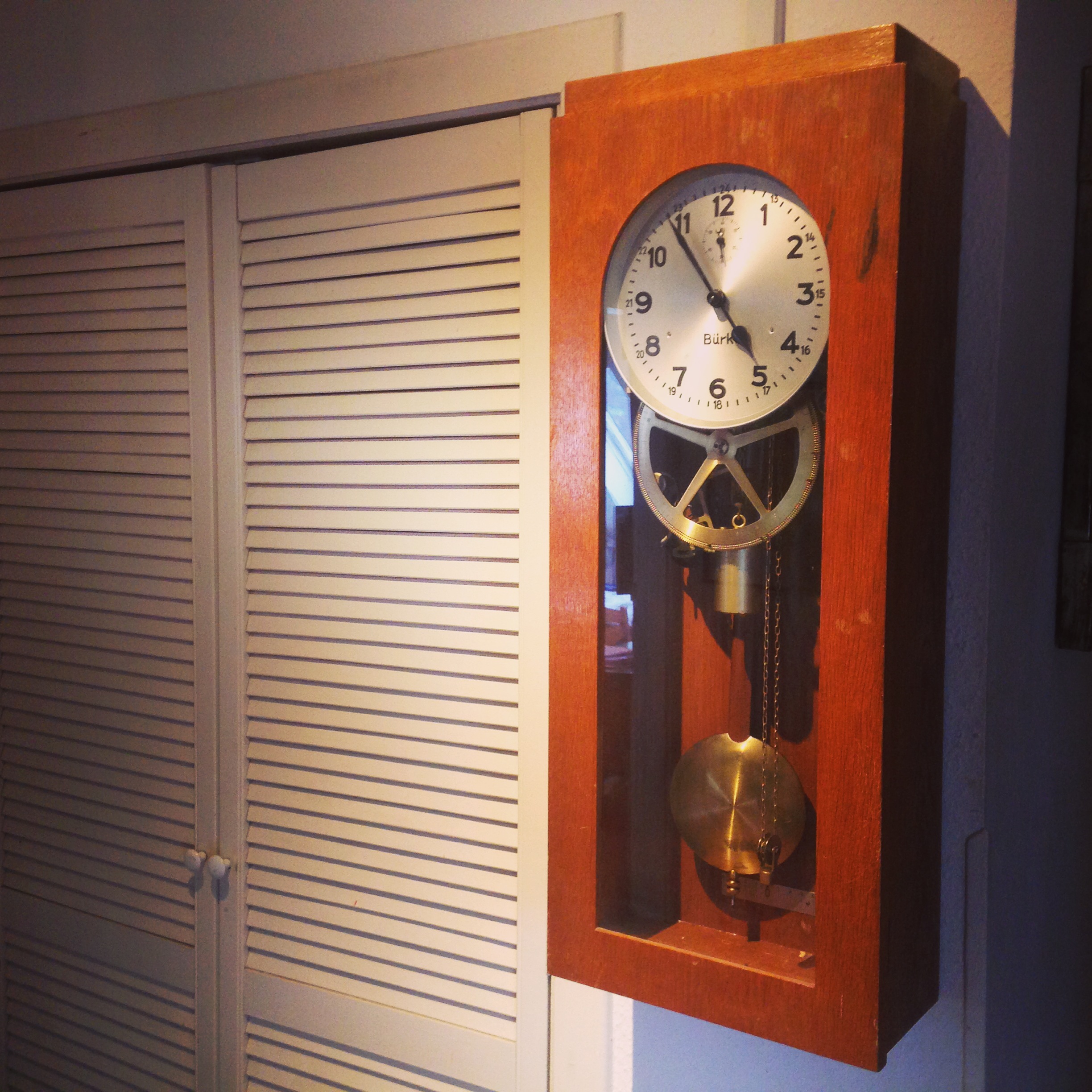
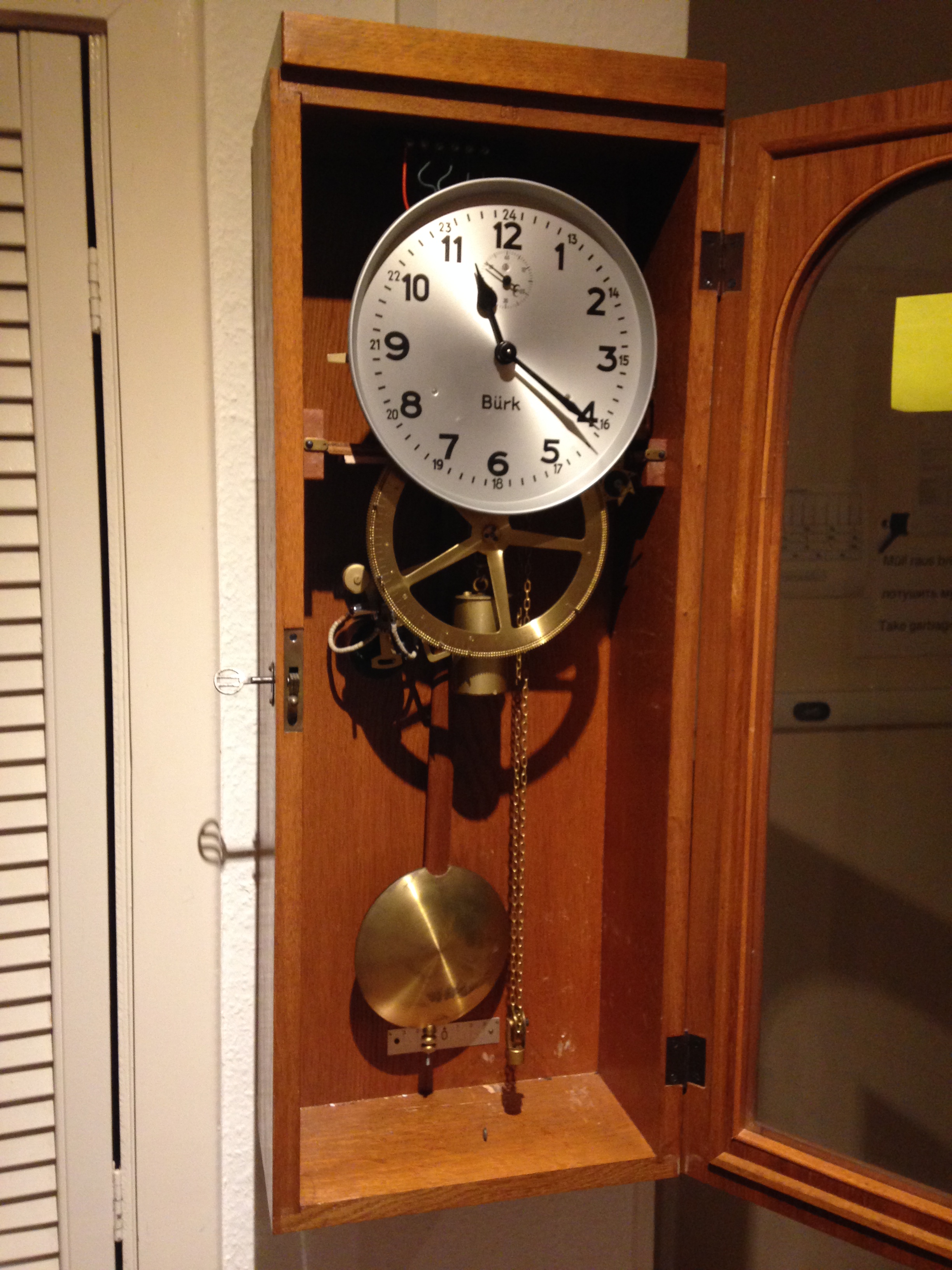
The Bürk Mutteruhr has been running very well for months now. The pendulum was repaired by a local clock maker for around €30 (see Part I). It keeps good time. I have it mounted on the wall in the hallway and have wired three slave clocks (Nebenuhren) around the house. We have Cat5e all through the house connected to a central patch panel. This made the connections relatively easy and tidy.
Setting the clock
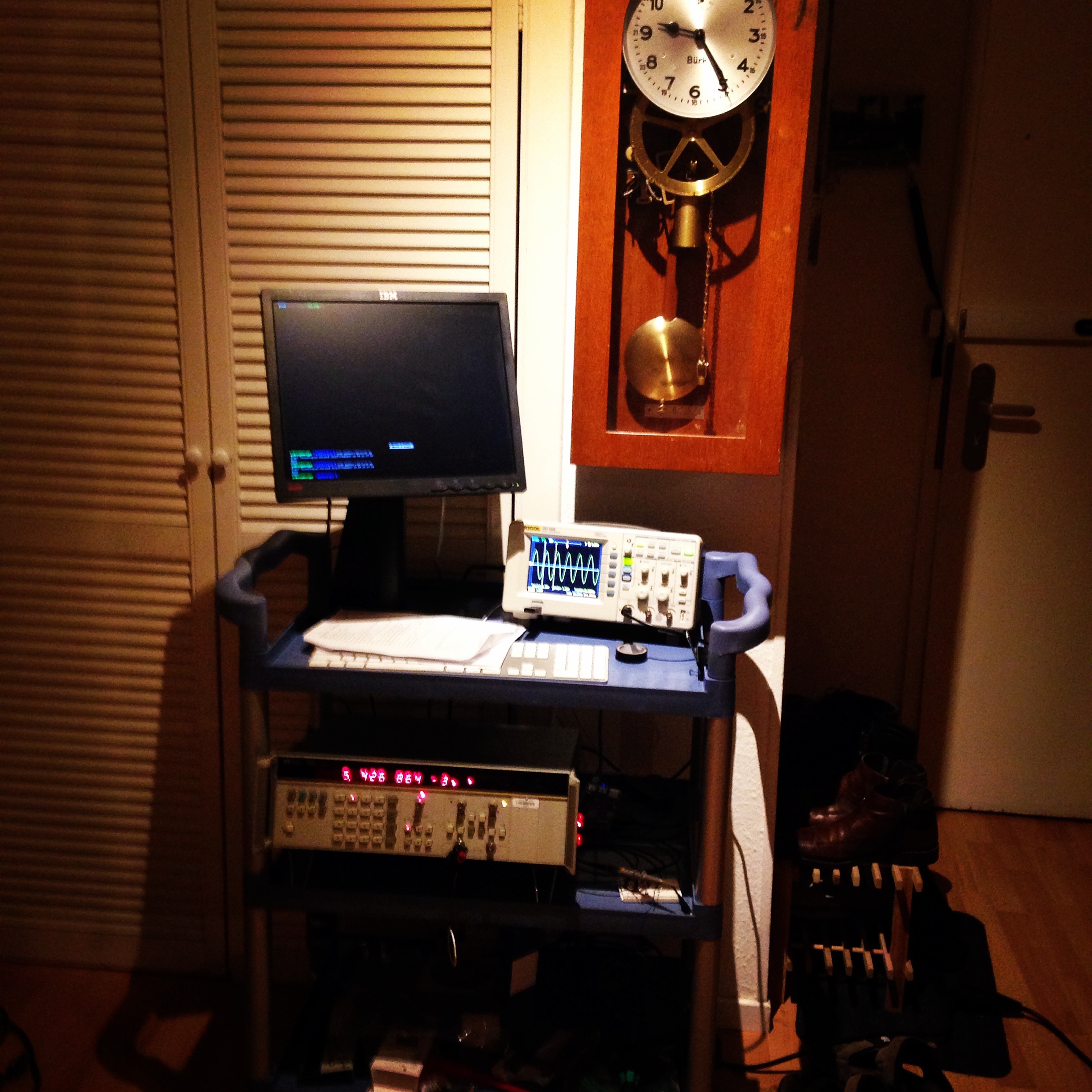
I used an iPhone app called ClockMaster to adjust both the level of the clock (to set the Δ, delta, to as close to zero as possible) and the clock rate through the adjustment of the regulating nuts. At times I have also attempted to manually keep a running record of a comparison between this clock and a Trimble Thunderbolt GPS Disciplined Oscillator. I am quite eager to setup an automatic measurement system to analyze the stability of the pendulum and overall accuracy of the clock. Unsurprisingly, variation in ambient temperature have their influence on the speed of the clock. This is especially noticeable after extremely hot days and in winter when the heating system switches into night time mode and a lower temperature.
Measuring clock accuracy
I would like to eventually add a datalogger temperature sensor and possibly a resistor based heating system to stabilize the temperature within the clock cabinet, so as to reduce the effects of the ambient temperature on the pendulum.
In addition I plan to use a HP5328B general purpose counter to examine the variation in the oscillation of the pendulum as well as the overall accuracy of the clock over longer periods. For this I need a USB to GPIB interface. I would like to use a RaspberryPi and the USB to GPIB interface to do the work. I have other priorities at the moment, but that is on the list.
How should I get sensor data into the HP5328B counter?
While I have you, I am quite interested in finding a way for detecting the tick tock of the clock escapement to trigger the HP5328B general purpose counter. There is another ‘loud’, but perhaps not as loud, clicking noise inside the mechanism. These are caused by the mechanism that triggers the once a minute pulse to the slave clocks. This makes a couple of regular clicking sounds. This would surely disturb data collection without proper filtering. I plan to use a large piezo element attached to the clock mechanism to detect the tic and tock. It is my hope that I can place the piezo as close to the shaft of the escapement and as far from the slave trigger mechanism as possible.
Do you have a better idea?
Do you have any ideas on filtering the piezo sensor?
I would really appreciate any ideas you have, so please leave a comment.
Alternatively, and in the meantime, I plan to measure the once a minute pulse for the slave clocks. In any event I still need to get hold of a €150 USB to GPIB to record the data.
Please let me know your thoughts!
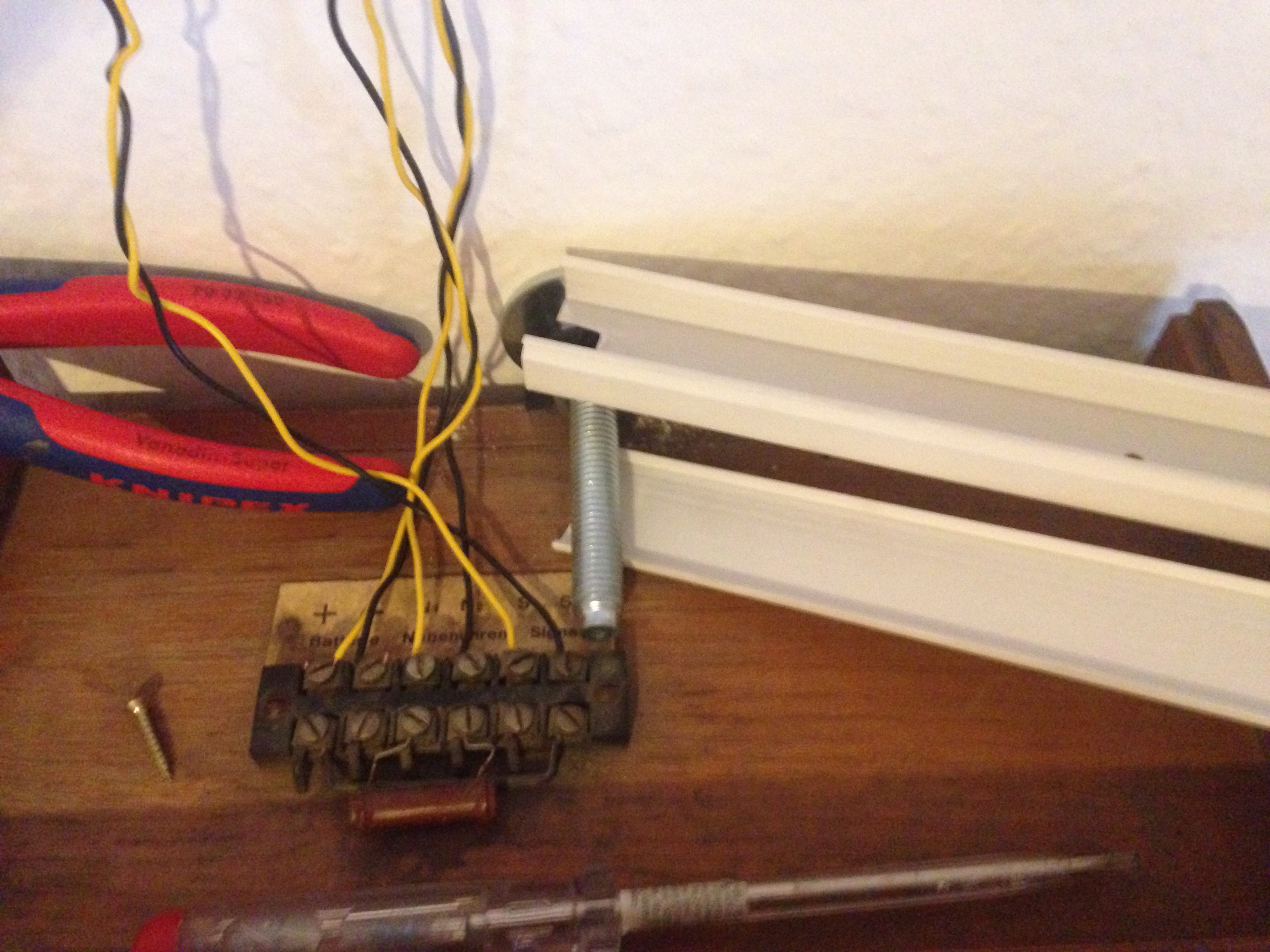
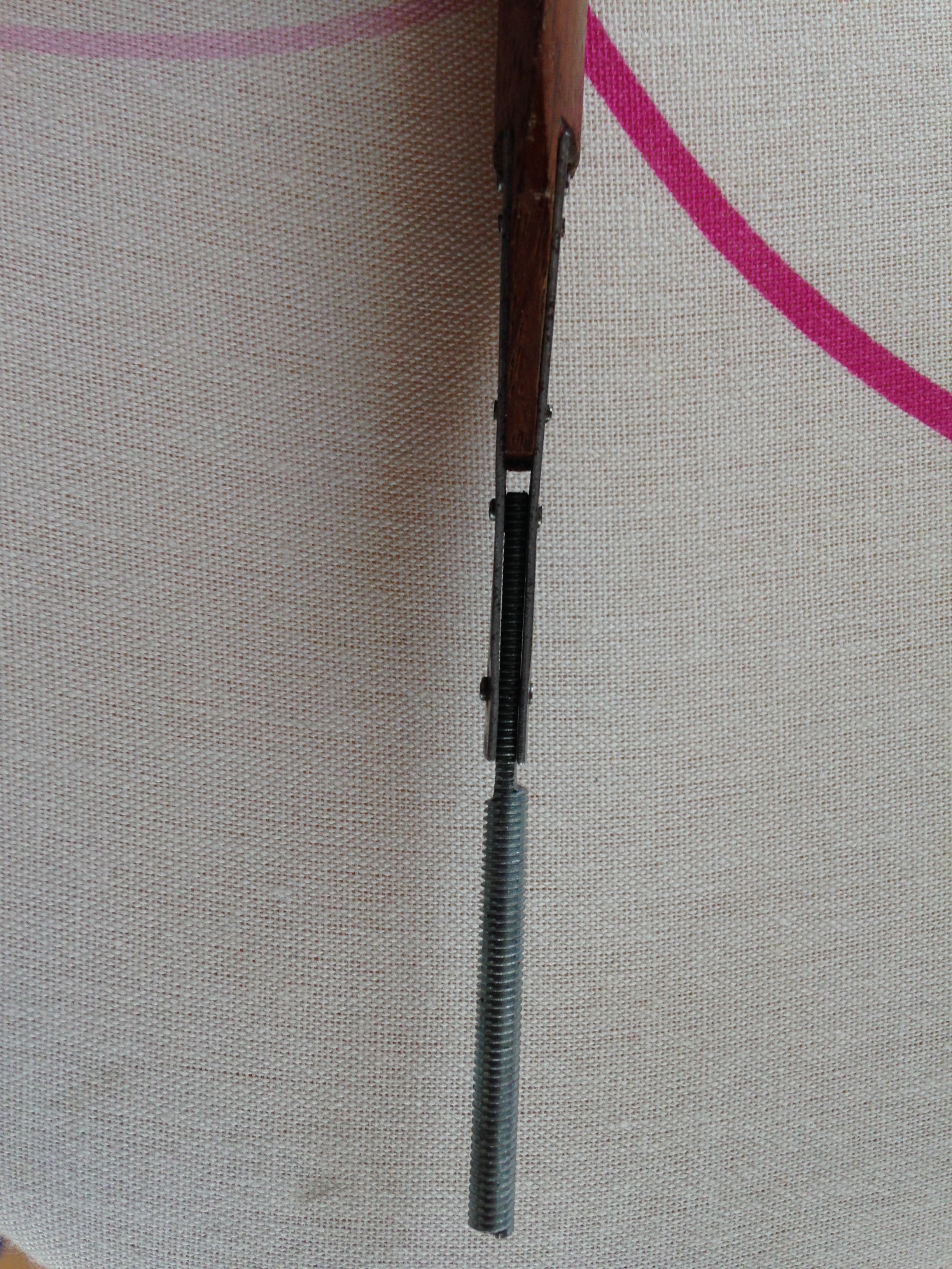
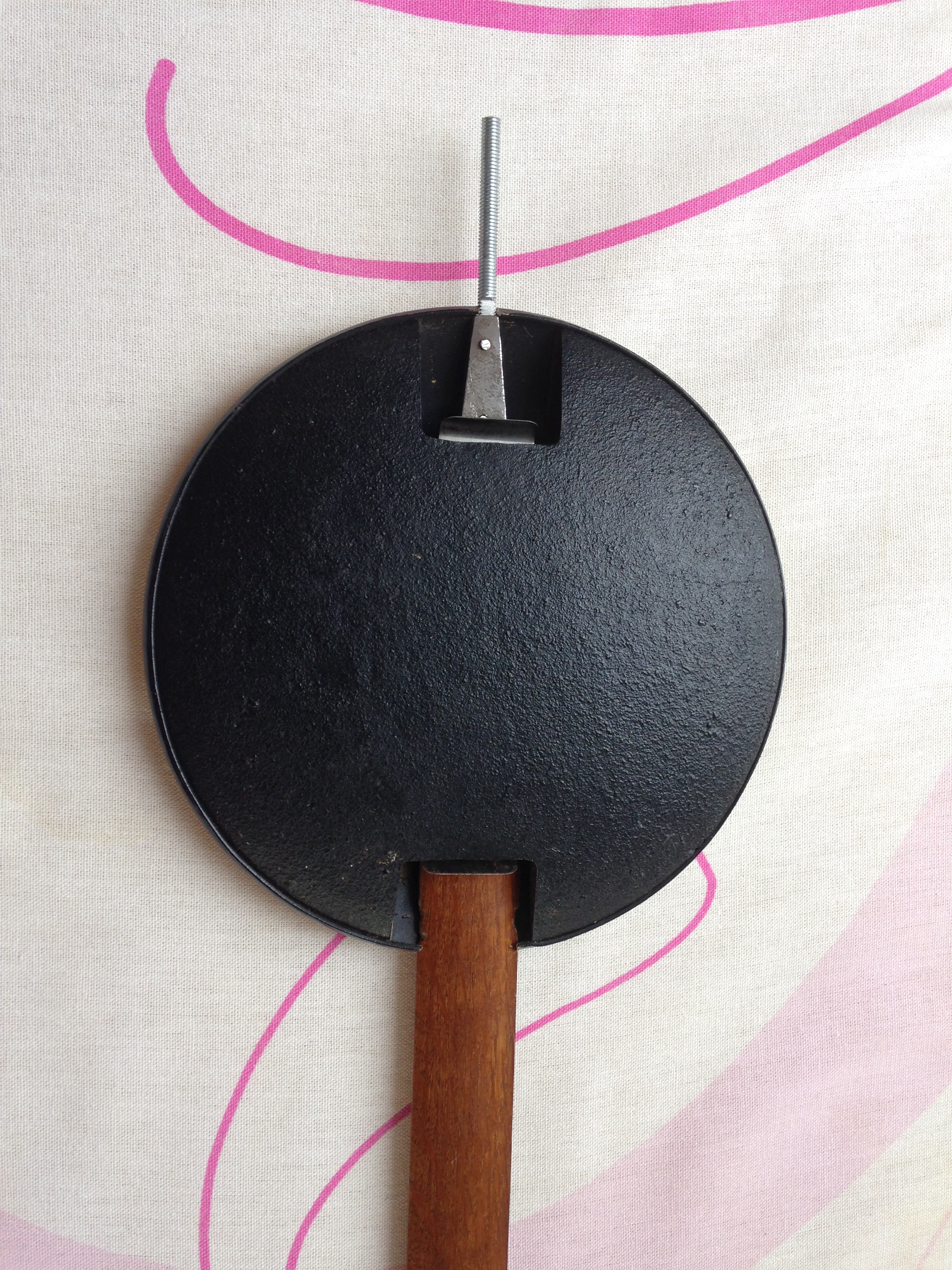
Here are some photos of the clock project, including the repaired pendulum regulator thread (click to enlarge). You’ll see a six way terminal block on top of the clock case. These are 12v positive, 12v negative, slave clock line A, slave clock line B, and two terminals connected to the timer switch wheel mechanism to activate, say, a school bell.


Hi, I have the exact same clock and I need the dimensions and weight of the pendulum rod and weight, and the weight cylinder.
Please, I want to make them.
Thank you
Dan
LikeLike
buena tarde escribo desde Coatzacoalcos, veracruz . Mexico tengo un reloj burk que rescate de una bodega abandonada y quisiera repararlo, podría porfavor mandarme fotos de la instalación eléctrica de reloj .. o como conecto usted todos los cables, sería de una ayuda enorme muchas gracias
LikeLike
Check your hotmail Luis.
LikeLike