Created 3 June 2016
Table of Contents
1. Part I – Introduction (this page)
2. Part I (A) – Rough stability measurements
Why?
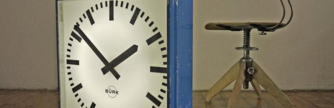
The goal of this project is characterize the pendulum in my Bürk master clock. I do not know how stable this clock is. The motivation for this project is to learn more about pendulums as well as the tools necessary for collecting and processing data about the pendulum. I am no expert in any of this and my approach could be wrong or have some serious flaw that is obvious to someone more knowledgeable than me about these things. If you think I have made a mistake or could do something better I would greatly appreciate hearing from you through the comments or the contact page.
One of the motivations for writing up this project is that I have been unable to find a consolidated source explaining the practicalities of how to ‘characterize’ a clock pendulum. There are many resources out there but I wasn’t able to find a dummies guide on how to do actually do this. Maybe it’s just too obvious for those more experienced than I.
I have been planning this project in my spare time for about a year now. I will be posting about my progress gradually. Each post should be about one step in the process or component in the system.
The next post will be Pendulum characterization Part II – The swing detector
My approach to this project is nothing new. Over the last year I have been reading various websites and blog posts about pendulums, precision clocks and general purpose electronic counters like my HP5335A and 5328B.
The sensor
Initially I planned to obtain the data from the clock by using a piezo electric pick up attached to the clock mechanism as close to the escapement as possible. This would detect the tick and tock of the clock and allow me to determine if the clock was in beat and how so. However, as this is a master clock for driving slave dials, it contains other mechanical parts for sending the once per minute impulses. These parts do make regular noises and I fear that they would also be picked up by the piezo element. There may be a way to filter these out physically or in the subsequent collected data. I plan to experiment with the piezo pick up in due course. However, for now I will be using a photo interrupter to detect a small pin I will attach at the bottom of the pendulum on the thread for the regulation nuts. This method will not allow me to determine the beats of the escapement. Instead it will allow me to determine the precise period of the pendulum.
The measurement apparatus
I have sought the advice of an expert in oscillator characterization as there were gaps in my understanding that I was unable to fill. He’s been very helpful. More on these problems in subsequent posts.
One interesting fact I have since learned is the shortcomings of time interval counters (TICs), like the HP5335A Universal Counter, for my intended purpose. The problem stems from the minimum dead time specification of a counter. Modern counters seem to have overcome this issue from what I understand, but my 1970s vintage counter with its minimum time between the stop and start of a time interval measurement means that there will be gaps between each pendulum period.
Measurements with these gaps will still yield useful information however, in the words of the expert, the measurements will be statistical rather than actual. There is a surprisingly (for me) simple alternative method using a PIC micro-controller to obtain event data from a photo interrupter that avoids this problem.
Another method explained to me, which would be obvious to anyone with more knowledge than me on this topic, is to use the TIC to measure the difference in phase between a reference oscillator and my pendulum. This is interesting to me and still allows me to make use of my counter toys/investment. I will explain this method and the PIC option in Part II or III.
